 |
| PanelMax |
 |
| PanelMax Vertex |
 |
| Panelmax Prusa |
This is a guide to building and setting up the electronic components of PanelMax as described here and here.
1 Requirements:
- A Reprap 3D Printer :-p
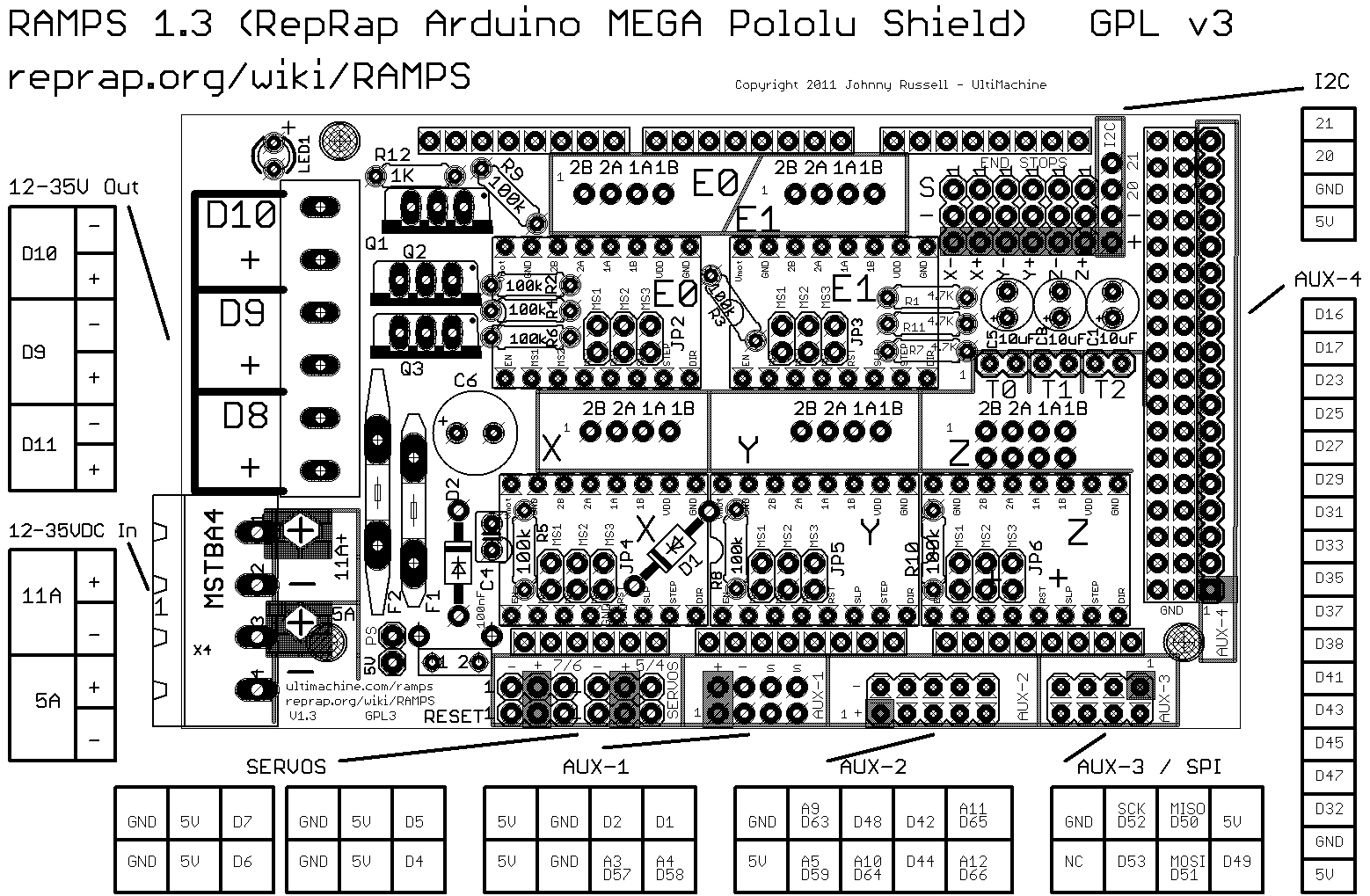
- RAMPS hardware 1.3 or 1.4 (1.2 should work as well but this guide will focus on 1.3/1.4)
- Marlin firmware Version 1.0 RC2 or above.
- A good soldering iron.
- Some basic knowledge of electronics, if you can build your own reprap, you are more than qualified.
- PanelMax RP parts you need at least the pm_encoder_shield part printed.
- Panelmax Vertex or Panelmax Prusa need the front piece printed.
Let's get started.
This is the basic schematic used in my setup.

2 SDcard reader

These are the the SDcard reader components that comes with my kit, if you are sourcing the parts yourself, this is where to find the reader http://www.dfrobot.com/index.php?route=product/product&product_id=163. It is a 5V part that works directly with the Arduino. (Note, please ignore the 0.01uf capacitor. That is the tiny yellow capacitor at the upper right of this picture)
If you already own a SDRAMPS or planning to get one, that should work too but you will have change the panelmax enclosure to fit SDRAMPS.
2.1 SDCARDDETECT Hack (This hack is already done on all kits sold after April 5)

This is pretty much the only tricky bit of soldering in the whole assembly process. Neither the SD module here nor sdramps has the SDCARDDETECT pin routed anywhere, so to get the SDCARDDETECT signal, we have to solder a wire to the sdcard cage. on this module, it is the 2nd pin from the bottom. (2nd pin from the right on this picture).
Take the red wire (black in some kits) cut a 10 cm section from the crimp side and solder it onto the the SDCARDDETECT, leave the rest for later use. Pre tin the wire tip and use plenty of flux when you do the soldering.

This is how it should look when done. More pics here and here. I would also secure the wire to the module with some hot glue as shown in the picture.
(Once again, please ignore the 103 cap in the picture, it create more problem than it solves. So just discard it.)
2.2 Cable
The SD card cable has 6 wires, Just crimp each end of the cable with one type of crimp terminals. (there are 2 types of crimp terminals for this cable)

If you don't trust your crimping tool, it may be a good idea to put a tiny bit of solder on the wire contact of each crimp. it is very annoying if the wires get pull out.
(April 10, 2012 New kits ships with a different cable, if yours is of a different color scheme, please go to section 2.2.2)
2.2.1 Original SD Card Ribbin cable.


Insert the crimps to their housing on the other end of the cable. Kit users follow the color code and the cable is now ready. if you are self sourcing, please check the schematic for pin position.
2.2.2 New Style SD Card Ribbin cable.


Insert the crimps to their housing on the other end of the cable. Kit users follow the color code and the cable is now ready. if you are self sourcing, please check the schematic for pin position.

The SD Card Reader is now ready.
3 LCD Display


Lets get started by linking up the ground/grounded pins, we want to connect pin 1, pin 3, pin 5 and pin16 on the upper pads.

This resistor controls the brightness of the backlit LED. 1.8k seems best to me and is the brightness you see in the picture/video of the panelmax I posted. You can change it to any other value between 0 and 10k. If I can source some sanely priced trimmer, i may include them instead of the resistor in later kits.

Again, follow the color coding scheme and you will have the pins connected correctly.
If you are self sourcing, you will need 9 wires, follow the schematic for pin connection and please remember pin 8 on AUX2 (D42) is for SDCARDDETECT.
3.2 Connecting SDCARDDETECT

Then thread it into the crimp terminal on the SDcard reader like this, remember to put in the bigger heat shrink tube too.

Use a pair of pliers to fix the orange cable in and solder them together for good.


Finish off by covering the join with some heat shrink tube.


Finally cut off the extra green wire so that it doesn't short anything.
This is what it should look like when it is done.

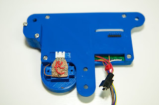
4 Click Encoder

These are all the components for the click encoder assembly.

First we crimp the ends of the 3 wire cable. There is no color coding for this cable, each kit may come with different color wires. Again, it is a good idea to put a tiny bit of solder on the crimps to secure them.
 Plug the crimps into the housings, there is no particular order here, just don't cross the wires.
Now, take the click encoder and align the pins onto the perforated broad. Mark the case ground positions with a pencil then drill 2 holes for them to pass through.

Carefully insert the click encoder onto the perforated board, after it's in all the way, bend the leads inword and solder it to the board.


Trim off the excess until it look like this.

Solder the white socket onto the board. Try to make the leads touch 2 copper pads for better structural integrity.

Wire the ground wire like this.

Then connect the signal pins to the socket.
4.1 Special note for PanelMax Vertex and PanelMax Prusa
For PanelMax Vertex and PanelMax Prusa, you will need to trim your click encoder board smaller. Something like the one in the following picture will work fine.

Click encoder wiring is now done, except for the ground, which doesn't go anywhere at the moment. we will address that in the next section.

5 Reset Button

The reset button is more or less the most important button on the panelmax. When you are doing hostless printing, this is the only thing that can stop the printer quickly when you have an "Oh-Shit" moment. So if you are self sourcing, please do include this in your setup.

To continue with this guide, you need to print a pm_encoder_shield from thingiverse.


Now, cut a 10-15 cm off the other end of the wire, crimp and install crimp housing. Make sure the wire matches when you plug them together.


Plug the push button and click encoder into the shield like this.

 Note that the push button from the kit has 4 contacts, we will not be using the contacts that has the + and - marking, they are for the build in 5V LED. If you like a glowing reset button, you can wire an extra 5V line to it, but i find it distracting.
 Next cut a 10 cm section of unused wire, solder it to one of the contacts on the push button(do not use the contacts with + and - marking) along with the ground side of the reset cable.
 Solder the other wire in the reset cable to the the reset button and solder the free ground wire to the ground contact on the click encoder.
 Ok, panelmax is now done. All we need to do now is plugging it
6 Plugging it all in.
 This is how we connect the click encoder and reset button, the click encoder plugs into the SERVOS headers on ramps.
 The LCD cable plugs into AUX2, if you are using my kit, just follow the color coding and you are all done, otherwise, please refer to the schematic for proper pin connection.
The SDcard Reader cable goes to the AUX3/SPI header. Once again, kit user follow the color coding for the 2 plugs and you should be done.
Please follow the set of picture corresponding to your SD Card Reader cable color scheme
Original


New Style


Here are a couple of pictures showing everything together.


IMPORTANT for RAMPS 1.3
If you are using RAMPS 1.3, you need to connect the click encoder wire to the D4, D5 and D6 on the SERVO port. Middle wire goes to D5, the rest goes to D4 and D6.
6.1 Additional Info for PanelMax Vertex and PanelMax Prusa
1.) Insert the push button into the cutout before soldering the wires on.
2.) There is a channel for the ground wire to go to the click encoder, check pics below.

Route the wire through the cutout beside the reset button.

Thread the ground wire through the small cutout beside the click encoder mount.
Solder the ground wire onto the click encoder's ground connection.

 This is how you plug in the SD Card Reader cable. Picture shows the new style cable.
If you haven't done so, check out the latest marlin form https://github.com/ErikZalm/Marlin.git
Apply your usual setting changes to it then make the following additional ones for panelmax.
Preassembled PanelMax available here
http://ebayitem.com/150848171067
If you have any questions please find me on irc #reprap, #mendelmax (tommyc_mac or tommyc_air), on thingiverse or email me at tommyc(at)tczone(dot)org.


Plug the push button and click encoder into the shield like this.


 Next cut a 10 cm section of unused wire, solder it to one of the contacts on the push button(do not use the contacts with + and - marking) along with the ground side of the reset cable.

6 Plugging it all in.


The SDcard Reader cable goes to the AUX3/SPI header. Once again, kit user follow the color coding for the 2 plugs and you should be done.
Please follow the set of picture corresponding to your SD Card Reader cable color scheme
Original


New Style


Here are a couple of pictures showing everything together.


IMPORTANT for RAMPS 1.3
If you are using RAMPS 1.3, you need to connect the click encoder wire to the D4, D5 and D6 on the SERVO port. Middle wire goes to D5, the rest goes to D4 and D6.
6.1 Additional Info for PanelMax Vertex and PanelMax Prusa
1.) Insert the push button into the cutout before soldering the wires on.
2.) There is a channel for the ground wire to go to the click encoder, check pics below.

Route the wire through the cutout beside the reset button.

Thread the ground wire through the small cutout beside the click encoder mount.

Solder the ground wire onto the click encoder's ground connection.

Secure the click encoder and plug in the wire. (no color scheme here, just don't cross the wires.)
 This is how you plug in the SD Card Reader cable. Picture shows the new style cable.
7 Firmware
If you haven't done so, check out the latest marlin form https://github.com/ErikZalm/Marlin.git
Apply your usual setting changes to it then make the following additional ones for panelmax.
7.1 Configuration.h
Make sure you are using MOTHERBOARD=33
Scroll to the bottom of the file and make the highlighted changes.
//===========================================================================
//=============================Additional Features===========================
//===========================================================================
// EEPROM
// the microcontroller can store settings in the EEPROM, e.g. max velocity...
// M500 - stores paramters in EEPROM
// M501 - reads parameters from EEPROM (if you need reset them after you changed them temporarily).
// M502 - reverts to the default "factory settings". You still need to store them in EEPROM afterwards if you want to.
//define this to enable eeprom support
#define EEPROM_SETTINGS
//to disable EEPROM Serial responses and decrease program space by ~1700 byte: comment this out:
// please keep turned on if you can.
#define EEPROM_CHITCHAT
//LCD and SD support
//#define ULTRA_LCD //general lcd support, also 16x2
//#define SDSUPPORT // Enable SD Card Support in Hardware Console
//#define ULTIMAKERCONTROLLER //as available from the ultimaker online store.
#define ULTIPANEL //the ultipanel as on thingiverse
#ifdef ULTIMAKERCONTROLLER //automatic expansion
#define ULTIPANEL
#define NEWPANEL
#endif
#ifdef ULTIPANEL
#define NEWPANEL //enable this if you have a click-encoder panel
#define SDSUPPORT
#define ULTRA_LCD
#define LCD_WIDTH 20
#define LCD_HEIGHT 4
// Preheat Constants
#define PLA_PREHEAT_HOTEND_TEMP 180
#define PLA_PREHEAT_HPB_TEMP 70
#define PLA_PREHEAT_FAN_SPEED 255 // Insert Value between 0 and 255
#define ABS_PREHEAT_HOTEND_TEMP 210
#define ABS_PREHEAT_HPB_TEMP 110
#define ABS_PREHEAT_FAN_SPEED 255 // Insert Value between 0 and 255
#else //no panel but just lcd
#ifdef ULTRA_LCD
#define LCD_WIDTH 16
#define LCD_HEIGHT 2
#endif
#endif
7.1.1 Configuration_adv.h
Look for the the following section, make sure you commented out #define SDCARDDETECTINVERTED// If you are using a RAMPS board or cheap E-bay purchased boards that do not detect when an SD card is inserted// You can get round this by connecting a push button or single throw switch to the pin defined as SDCARDCARDDETECT // in the pins.h file. When using a push button pulling the pin to ground this will need inverted. This setting should// be commented out otherwise// #define SDCARDDETECTINVERTED
7.2 pins.h
Scroll to Arduino Mega pin assignment and make the following changes./****************************************************************************************
* Arduino Mega pin assignment
*
****************************************************************************************/
#if MOTHERBOARD == 3 || MOTHERBOARD == 33 || MOTHERBOARD == 34
#define KNOWN_BOARD 1
//////////////////FIX THIS//////////////
#ifndef __AVR_ATmega1280__
#ifndef __AVR_ATmega2560__
#error Oops! Make sure you have 'Arduino Mega' selected from the 'Tools -> Boards' menu.
#endif
#endif
// uncomment one of the following lines for RAMPS v1.3 or v1.0, comment both for v1.2 or 1.1
// #define RAMPS_V_1_3
// #define RAMPS_V_1_0
#if MOTHERBOARD == 33 || MOTHERBOARD == 34
#define X_STEP_PIN 54
#define X_DIR_PIN 55
#define X_ENABLE_PIN 38
#define X_MIN_PIN 3
#define X_MAX_PIN 2 //2 //Max endstops default to disabled "-1", set to commented value to enable.
#define Y_STEP_PIN 60
#define Y_DIR_PIN 61
#define Y_ENABLE_PIN 56
#define Y_MIN_PIN 14
#define Y_MAX_PIN 15 //15
#define Z_STEP_PIN 46
#define Z_DIR_PIN 48
#define Z_ENABLE_PIN 62
#define Z_MIN_PIN 18
#define Z_MAX_PIN 19
#define E0_STEP_PIN 26
#define E0_DIR_PIN 28
#define E0_ENABLE_PIN 24
#define E1_STEP_PIN 36
#define E1_DIR_PIN 34
#define E1_ENABLE_PIN 30
#define SDPOWER -1
#define SDSS 53
#define LED_PIN 13
#if MOTHERBOARD == 33
#define FAN_PIN 9 // (Sprinter config)
#else
#define FAN_PIN 4 // IO pin. Buffer needed
#endif
#define PS_ON_PIN 12
#define KILL_PIN 31
#define HEATER_0_PIN 10 // EXTRUDER 1
#if MOTHERBOARD == 33
#define HEATER_1_PIN -1
#else
#define HEATER_1_PIN 9 // EXTRUDER 2 (FAN On Sprinter)
#endif
#define HEATER_2_PIN -1
#define TEMP_0_PIN 13 // ANALOG NUMBERING
#define TEMP_1_PIN 15 // ANALOG NUMBERING
#define TEMP_2_PIN -1 // ANALOG NUMBERING
#define HEATER_BED_PIN 8 // BED
#define TEMP_BED_PIN 14 // ANALOG NUMBERING
#ifdef ULTRA_LCD
#ifdef NEWPANEL
//arduino pin which triggers an piezzo beeper
#define BEEPER 32 // Beeper on AUX-4
#define LCD_PINS_RS 63
#define LCD_PINS_ENABLE 65
#define LCD_PINS_D4 59
#define LCD_PINS_D5 64
#define LCD_PINS_D6 44
#define LCD_PINS_D7 66
//buttons are directly attached using AUX-2
#define BTN_EN1 6
#define BTN_EN2 5
#define BTN_ENC 4 //the click
#define BLEN_C 2
#define BLEN_B 1
#define BLEN_A 0
#define SDCARDDETECT 42
//encoder rotation values
#define encrot0 0
#define encrot1 2
#define encrot2 3
#define encrot3 1
#else //old style panel with shift register
//arduino pin witch triggers an piezzo beeper
#define BEEPER 33 No Beeper added
//buttons are attached to a shift register
// Not wired this yet
//#define SHIFT_CLK 38
//#define SHIFT_LD 42
//#define SHIFT_OUT 40
//#define SHIFT_EN 17
#define LCD_PINS_RS 16
#define LCD_PINS_ENABLE 17
#define LCD_PINS_D4 23
#define LCD_PINS_D5 25
#define LCD_PINS_D6 27
#define LCD_PINS_D7 29
//encoder rotation values
#define encrot0 0
#define encrot1 2
#define encrot2 3
#define encrot3 1
//bits in the shift register that carry the buttons for:
// left up center down right red
#define BL_LE 7
#define BL_UP 6
#define BL_MI 5
#define BL_DW 4
#define BL_RI 3
#define BL_ST 2
#define BLEN_B 1
#define BLEN_A 0
#endif
#endif //ULTRA_LCD
#else // RAMPS_V_1_1 or RAMPS_V_1_2 as default
#define X_STEP_PIN 26
#define X_DIR_PIN 28
#define X_ENABLE_PIN 24
#define X_MIN_PIN 3
#define X_MAX_PIN -1 //2
#define Y_STEP_PIN 38
#define Y_DIR_PIN 40
#define Y_ENABLE_PIN 36
#define Y_MIN_PIN 16
#define Y_MAX_PIN -1 //17
#define Z_STEP_PIN 44
#define Z_DIR_PIN 46
#define Z_ENABLE_PIN 42
#define Z_MIN_PIN 18
#define Z_MAX_PIN -1 //19
#define E0_STEP_PIN 32
#define E0_DIR_PIN 34
#define E0_ENABLE_PIN 30
#define SDPOWER 48
#define SDSS 53
#define LED_PIN 13
#define PS_ON_PIN -1
#define KILL_PIN -1
#ifdef RAMPS_V_1_0 // RAMPS_V_1_0
#define HEATER_0_PIN 12 // RAMPS 1.0
#define HEATER_BED_PIN -1 // RAMPS 1.0
#define FAN_PIN 11 // RAMPS 1.0
#else // RAMPS_V_1_1 or RAMPS_V_1_2
#define HEATER_0_PIN 10 // RAMPS 1.1
#define HEATER_BED_PIN 8 // RAMPS 1.1
#define FAN_PIN 9 // RAMPS 1.1
#endif
#define HEATER_1_PIN -1
#define HEATER_2_PIN -1
#define TEMP_0_PIN 2 // MUST USE ANALOG INPUT NUMBERING NOT DIGITAL OUTPUT NUMBERING!!!!!!!!!
#define TEMP_1_PIN -1
#define TEMP_2_PIN -1
#define TEMP_BED_PIN 1 // MUST USE ANALOG INPUT NUMBERING NOT DIGITAL OUTPUT NUMBERING!!!!!!!!!
#endif
// SPI for Max6675 Thermocouple
#ifndef SDSUPPORT
// these pins are defined in the SD library if building with SD support
#define MAX_SCK_PIN 52
#define MAX_MISO_PIN 50
#define MAX_MOSI_PIN 51
#define MAX6675_SS 53
#else
#define MAX6675_SS 49
#endif
#endif
That's it. Flash your arduino with this and your panelmax should work like the one in my video.
7.3 Files
These are my Configuration.h and pins.h in case you want to take a look.
8 Troubleshooting.
- If you don't use PID, you will need the latest github version of Marlin (Mar 25, 2012 or later will be fine), otherwise you may get a compilation error.
- If your LCD constantly flickers between status display and the main menu as soon as the RAMPS board is power on, check Configuration.h and make sure "MOTHERBOARD=33"
I will put stuff here as they come up. Cheers.
9 Shameless Self Promotion
Interested in purchasing a PanelMax kit? Please check my ebay listing http://ebayitem.com/150886149485Preassembled PanelMax available here
http://ebayitem.com/150848171067
If you have any questions please find me on irc #reprap, #mendelmax (tommyc_mac or tommyc_air), on thingiverse or email me at tommyc(at)tczone(dot)org.
Awesome job, I have to get one of these!
ReplyDeleteJust a little note. I was the originator of the SDcardinverted bit of code. It was created as a workaround to get SD cards with out a detect pin to work.
ReplyDeleteSince then I have changed the operation of Ramps so that if there is no SD Card detect pin, the card can be reinitialised via the refresh command in the LCD menu.
So if anyone feels nervous about adding the SD card detect cable as per your tutorial, it is no longer required to run from the SD card. Just set the SDCARDDETECT pin in pins.h to -1. That should fix it.
I like your project, very cool.
ReplyDeletethere's only one thing i don't like..
Why do you use a parallel display instead of an serial one?
Just one pin to use .. way better!
Because Marlin only support parallel mode LCD at the moment.
DeleteIs it possible to make it work on an Sanguinololu?
ReplyDeletenop, because Sanguinololu only has 64k of flash memory and Marlin with the panel code enabled will be 80k+ in size.
DeleteI plan to build this using a sanguinololu, but I will be using the Atmega 1284 which has 128K Flash and should have just enough pins. I'll keep you all updated.
Deletepin wise, yes should be just enough. hopefully none of them are reserved by marlin.
DeleteThis works on Sanguinololu with a 1284P, for example with the firmware changes required check out:
Deletehttp://blog.think3dprint3d.com/2012/06/sanguinololu-lcd-and-rotary-encoder.html
Great work, thank you. With this installed, can the printer still be connected normally to Pronterface? Also, is it easy to adapt the SD RAMPS board to work with this? Any advice on how to do that? Thanks!
ReplyDeleteAdding the panel doesn't impede the functionality of the USB in any way, so Pronterface or any other Host software would work just fine.
DeleteYou can use SDRAMPS instead of the SD card reader i use, only thing is you will need to figure out how to do the SDCARDDETECT hack on SDRAMPS. i have no idea because i don't have a SDRAMPS to test. Another way is follow Justblair's method 2 comment above and do without the SDCARDDETECT pin.
Thanks Tommy. I have the SD RAMPS board installed on my RAMPS 1.4 and would like to add the panel without having to relocate and re-wire it. Sounds like that should work if I use the software refresh option as above.
DeleteYes, exactly.
DeleteI have modified an SDRAMPS to provide the SDCARDDETECT. It is the far right pin (9th) on the U$1 behind the LED. I removed the LED for better access and soldered a "wire-wrap" wire to the U$1 pin and soldered the other end to the pin [on the SDRAMPS] that connects to D49 (AUX-3). Merlin config was modified to set SDCARDDETECT to PIN 49. All else is as described above. The LED was put back in its original position. Works a treat.
DeleteJust got my ebay kit yesterday and it looks awesome. Thanks for doing such a great job with the instructions - it should be a snap. Found a 10k trimmer here:
ReplyDeletehttp://www.sparkfun.com/products/9806
and ordered some, being the control freak that I am... Now all I have to do is build my 3D printer so I can print the housing, LOL. It's completely my own design, from extruder to hotend - I have machine tools, hehehe : )
Could you please tell me where did you buy the button from? What is the diameter of the hole? Thank you.
ReplyDeleteHas anyone had an issue where the click encoder does not register any rotation? The click function works, but I can only get minimal response from the rotation (1 line item down). Any thoughts? I have double, triple and quadrupal checked my configuration.h, pins.h, and wiring and all match the images and description above.
ReplyDeleteThanks,
Try rotating the click encoder plug 180 degrees and plug back into the RAMPS, see if that works
DeleteTried that last night and found that the screen would flash between the main page and first sub menu page and would not respond to any input. I may try resoldering the encoder just to make sure it was done correctly. I've also been having difficulties with inserting the SD card causing the screen to dim and the thermistor temp to go wild. I think I can chalk that up, though, to the fact that the RAMPS kit I purchased from Ultimachine did not have the D1 diode for powering Arduino w/ the 12V power supply. Took me a while to figure that one out. The Arduino would only power up when the USB was plugged in, regardless of whether or not the 12V power was turned on.
DeleteCheck configuration.h again and make sure it is set to board #33, check with a multimeter that the ramps ground is indeed bought to the ground pin on the click encoder. D1 is needed if you want to power the whole printer with a 12V power supply and no USB connected.
DeleteOn my encoder at least, the two pin side is the encoder and the three pin side is the click switch. Center pin on that side is common internally and you don't need to use it. Check the spec sheet for your encoder. Use the wrong side and you get the symptoms listed above.
ReplyDeletePlease follow http://www.justblair.co.uk/Personal/attaching-a-lcd-display-and-rotary-encoder-to-a-ramps-controlled-reprap-printer.html or http://repraphd.blogspot.de/2012/03/lcd-upgrade.html for the PINs and use AUX4 for the LCD. AUX-3 is fine for SD. But we need AUX-1 for bluetooth.
ReplyDeleteEspecially cause the settings of jsutblair are already defined in marlin by default.
thanks.
Very cool, I've got the prusa version up and running, but I'm having a problem with the inputs. If I click the encoder without rotating, it goes to menu, and then another click back to view - ok I think. However, if I rotate it, it starts an endless loop of menu-view-menu etc and I can't stop it. Any ideas? Have I got "Unknown's" problem above of a weirdly wired encoder?
ReplyDeleteSorted it, it was me not realising I needed to close and reopen the arduino ide if I changed pins.h in an external editor. *facethwack* http://i.imgur.com/FshZS.jpg Almost done, I'm using a tiny pcb mount switch because that's all I had, so I'll print a big red button cap to glue on top. Great design, cheers :)
ReplyDeleteI just finished assembling my kit, it appears to work with the exception of the LCD displaying garbage on the 4th line of the display, any idea where to start looking for the issue?
ReplyDeleteActually it looks like the 57th character is truncated and nothing useful is displayed on any character after that, is it likely to be a bad LCD?
ReplyDeleteCan you post a picture?, i do see some odd characters on the 4th line after updating to the latest marlin from github.
DeleteI have only RAMPS 1.2 and I can't set MOTHERBOARD = 33. I try it before, but my RAMPS stop working. I already made an order and I know that I will have a lot of work to connect wires directly to pins. What modifications I need to use MOTHERBOARD=3?
ReplyDeleteMB=33 won't work for you, you will need to change the pin mappings in pins.h first, i haven't try putting a panelmax on 1.2, and i am not sure if it has enough free pins. Check the sections in pins.h regarding the ultipanel, you need to copy that to the section for ramps 1.2 and reassign the pins.
DeleteAny luck getting this to work with a Ramps 1.2? I'm thinking of buying the kit as well..
DeleteHi Tommy, I'm putting together a Mendelmax variant. I bought an assembled panelmax, wired it to my RAMPS 1.4, uploaded the firmware changes and powered it up. All I got on the LCD (which lit up) was 2 lines of squares where the characters should be. Do you have any idea what could be going wrong? I tried to be meticulous about everything.
ReplyDeleteI downloaded the latest Marlin build today and applied your changes. Configuration.h and Configuration_adv.h looked similar to your examples. Pins.h looked a little different but I made the relevant section look like your example:
Delete#ifdef ULTRA_LCD
#ifdef NEWPANEL
//encoder rotation values
#define encrot0 0
#define encrot1 2
#define encrot2 3
#define encrot3 1
#define BLEN_A 0
#define BLEN_B 1
#define BLEN_C 2
#define LCD_PINS_RS 63
#define LCD_PINS_ENABLE 65
#define LCD_PINS_D4 59
#define LCD_PINS_D5 64
#define LCD_PINS_D6 44
#define LCD_PINS_D7 66
#ifdef REPRAP_DISCOUNT_SMART_CONTROLLER
#define BEEPER 37
#define BTN_EN1 6
#define BTN_EN2 5
#define BTN_ENC 4
#define SDCARDDETECT 42
#else
//arduino pin which triggers an piezzo beeper
#define BEEPER 33 // Beeper on AUX-4
//buttons are directly attached using AUX-2
#define BTN_EN1 37
#define BTN_EN2 35
#define BTN_ENC 31 //the click
#define SDCARDDETECT -1 // Ramps does not use this port
#endif
#else //old style panel with shift register
//arduino pin witch triggers an piezzo beeper
#define BEEPER 33 No Beeper added
//buttons are attached to a shift register
// Not wired this yet
//#define SHIFT_CLK 38
//#define SHIFT_LD 42
//#define SHIFT_OUT 40
//#define SHIFT_EN 17
#define LCD_PINS_RS 16
#define LCD_PINS_ENABLE 17
#define LCD_PINS_D4 23
#define LCD_PINS_D5 25
#define LCD_PINS_D6 27
#define LCD_PINS_D7 29
//encoder rotation values
#define encrot0 0
#define encrot1 2
#define encrot2 3
#define encrot3 1
//bits in the shift register that carry the buttons for:
// left up center down right red
#define BL_LE 7
#define BL_UP 6
#define BL_MI 5
#define BL_DW 4
#define BL_RI 3
#define BL_ST 2
#define BLEN_B 1
#define BLEN_A 0
#endif
#endif //ULTRA_LCD
The results seem to be the same: Of the 4 lines of text in the LCD, the 2 center lines are lit up as blocks. There is no activity. Any thoughts?
Blocks on screen meaning that the LCD is power up and ready for software to send over stuff to display. Check your pin mappings, also, make sure R/W is either shorted to ground or connected to a pin that is set low all the time in software(this is handy if you want to play with other firmware that actually uses the R/W pin later on).
DeleteHello.
ReplyDeleteOn the screen I can not start or is difficult to maintain 100% the Feed Rater by the encoder changes in steps of two or three (99% 101% ...)
Can you change the resolution of the rotary encoder?
Puls style per Enc Rotatory
Thank you.
My display works for a while, maybe 1/2 hour or so, then becomes more and more garbled, to the point only a few characters are readable anymore. An Arduino reset will clear it up, but is there anything else I can do?? Is there a way to reset comm. on the LCD without resetting the Arduino?
ReplyDeleteThat happened to me.
ReplyDeleteI solved this by checking the connections tight, also in the arduino tightens well.
great info? what type of reset switch? Normally open or closed? Could you use the scrool wheen encoder from a mouse? It has the click switch as well.
ReplyDeleteThis comment has been removed by the author.
ReplyDeleteBest Places To Bet On Boxing - Mapyro
ReplyDeleteWhere To Bet On Boxing. It's poormansguidetocasinogambling.com a sports betting event 출장마사지 in which you bet on the outcome of a game. https://deccasino.com/review/merit-casino/ In the https://febcasino.com/review/merit-casino/ boxing world, https://tricktactoe.com/ each player must decide if or not to